
Heat pipes move massive amounts of thermal energy through a sealed device without a pump, motor, or compressor. They’re seen in demanding systems ranging from air conditioning equipment and supermarket refrigeration to electronics and data center cooling.
For engineers, the questions go deeper: How does a heat pipe work across changing loads? Which materials and working fluids fit the temperature? What limits the capacity?
In this guide, we break down the operating cycle, design choices, performance limits, applications, and specification data for heat pipe technology.
What Are Heat Pipes?
A heat pipe is a sealed, two-phase transfer device that uses evaporation, vapor flow, condensation, and liquid return to move energy from a heat source to a cool region.
Conventional heat pipes have three core components:
- Envelope: The sealed outer tube or vessel containing the internal pressure and protecting the working fluid.
- Wick: A porous structure along the inner wall that uses capillary action to return condensed liquid to the hot end.
- Working fluid: A liquid selected for the operating temperature that absorbs heat, becomes vapor, releases heat at the cooler end, and condenses.
Since latent heat carries a majority of the energy, a well-designed heat pipe system can produce high thermal conductivity with a small temperature drop. Effective conductivity can reach 200,000 W/m·K under the right conditions, which is thousands of times higher than solid copper. Actual results are shaped by geometry, orientation, fluid, wick design, temperature, and load.
How Do Heat Pipes Work?
The operating cycle features four repeating stages:
- Evaporation: The evaporator sits by the heat source; the working fluid absorbs thermal energy and changes from liquid to vapor.
- Vapor transport: The pressure difference between the warm evaporator and cooler condenser drives vapor through the hollow core.
- Condensation: At the condenser, the vapor releases latent heat to a heat sink, air stream, or coil, then returns to liquid.
- Liquid return: Capillary pressure in the wick draws liquid back to the evaporator. Gravity can assist or resist this fluid movement, depending on orientation.
Phase-change cycles transfer heat while keeping devices close to isothermal condition. Low thermal resistance and minimal temperature difference between the hot and cold sections are two of the biggest advantages. Additionally, the cycle doesn’t require external power for the heat-transfer action.
What Are Heat Pipes Filled With?
Heat pipes contain a controlled amount of working fluid, as well as a small vapor space. They aren’t filled solidly with liquid; during manufacturing, air and other non-condensable gases are removed before the envelope is sealed. At operating temperature, part of the charge exists as liquid, the other part vapor.
Some of the most common fluid and envelope pairings include copper and water, copper and methanol, aluminum and ammonia, and stainless steel with fluids selected for more corrosive temperature ranges. Copper-water heat pipes typically serve 25°C to 150°C applications. Copper-methanol designs support lower-temperature electronics cooling, while aluminum-ammonia systems are commonly seen in spacecraft.
Finding the right pairing is paramount, as the fluid must be chemically compatible with the envelope and wick. Poor matches can create corrosion, gas generation, deposits, or fluid loss, all of which raise the thermal resistance.
Heat Pipe Components and Materials
Envelope Selection
Copper is widely used, known for conducting heat well, being easy to form, and its compatibility with water across temperature ranges. Aluminum offers low mass and is frequently paired with ammonia. Stainless steel provides strength and chemical resistance for specialized service, but its lower wall conductivity needs to be considered.
Wall thickness, pressure rating, joining method, and permeability can also affect reliability over time. Envelopes have to tolerate internal vapor pressure at the highest expected temperature, plus shipping, vibration, and installation loads.
Wick Structures
Three of the most common wick types are sintered powder, grooved, and metal screen. Sintered wicks offer strong capillary pumping and can work across orientations. Grooved wicks feature low flow resistance and are relatively straightforward, but their capillary pressure is lower. Screen wicks strike the best balance of cost, permeability, and pumping capability.
Wick selection is a tradeoff; smaller pores create capillary pressure, while larger flow paths limit liquid pressure loss. An ideal design supplies enough pumping force without choking the returning liquid.
Operating Temperature and Boiling Point Considerations
Working fluid doesn’t need to reach its atmospheric boiling point. Rather, the sealed internal pressure sets the saturation temperature. For stable operation, working fluid should exist in saturated liquid and vapor states across the expected temperature band.
Selection tends to follow three steps. First, define the normal, minimum, startup, and maximum temperatures. Second, compare all candidate fluids for vapor pressure, latent heat, viscosity, surface tension, freezing point, and chemical compatibility. Third, check the resulting pressure, wick performance, and safety requirements across the entire range.
Copper-water designs suit 25°C to 150°C service, while cryogenic heat pipes use specialized fluids below -150°C. At the other end, alkali-metal heat pipes can operate around 400°C to 1,100°C. No single fluid can cover each range.
Performance Limits: Capillary Limit and Transport Capacity
The capillary limit is reached when the wick can’t produce enough pressure to overcome liquid, vapor, or gravity-related pressure losses. Once that occurs, the evaporator starts to dry out and the temperature rises.
Basic capacity checks should follow this sequence:
- Calculate the available capillary pressure from the fluid’s surface tension, contact angle, and effective wick pore radius.
- Estimate liquid pressure drop through the wick at the target heat load.
- Add the vapor pressure drop through the core and the gravity head for the installed orientation.
- Confirm that available capillary pressure is greater than the pressure loss, with an application-appropriate margin.
- Calculate thermal capacity with the system resistance: Q = ΔT / Rtotal.
- Engineers also check the sonic limit at startup, the viscous limit at low temperature, vapor-flow or entrainment limits at high velocity, boiling limits in the wick, and condenser capacity.
Types of Heat Pipes and Heat Pipe Technology
Constant-Conductance and Variable-Conductance Heat Pipes
A constant-conductance heat pipe provides passive heat transport over the designed range. A variable-conductance heat pipe, or VCHP, introduces a reservoir of non-condensable gas. As the temperature changes, the gas expands or contracts over part of the condenser, which changes the active condensing area and regulates temperature.
VCHPs are valued when equipment faces changing heat loads or sink temperatures, seeking tighter control than a fixed design can provide.
Loop Heat Pipes
Loop heat pipes separate liquid and vapor flow into dedicated lines, using a capillary evaporator to drive circulation. This architecture routes around components to carry energy farther than a short tubular device can.
Routing flexibility benefits dispersed electronics, telecom enclosures, satellites, aerospace hardware, and other systems where the heat source and rejection surface can’t sit close together. However, loop heat pipes still face capillary, pressure-drop, startup, and orientation requirements.
Vapor Chambers
A vapor chamber is a flat, two-dimensional heat pipe that spreads heat across a broad base before that energy enters a fin stack or cold plate. Tubular heat pipes efficiently move energy along a defined path. Vapor chambers are usually better for spreading concentrated processor heat, while tubes can connect separated hot and cold zones or weave through a compact assembly.
Integration With Heat Sinks and Heat Exchangers
Heat pipes can move energy away from a concentrated source, but they still require good contact with the source and a capable heat sink at the condenser. Engineers often bond or press tubes into an aluminum base and fin stack. Interface flatness, clamping pressure, thermal-interface material, tube spacing, fin area, and airflow can all affect the final result.
Published tests have reported roughly 20% improvement in air-cooled heat sink configurations, although the gain changes with airflow, source footprint, pipe placement, and baseline design. Model the complete thermal path rather than seeing the heat pipe’s effective conductivity as the system rating.
Heat Pipes in Air Conditioning and Energy Recovery
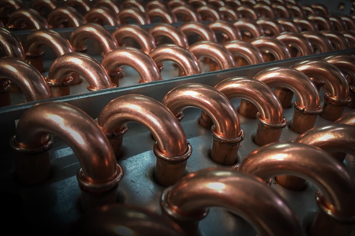
In air conditioning equipment, a wrap-around heat pipe places one module before the cooling coil and another one after it. The first module precools the incoming air, allowing the coil to remove more moisture. The second module uses recovered heat to reheat the leaving air, supporting lower supply-air humidity while reducing or eliminating active reheat.
For energy recovery, heat pipe modules bridge the separated supply and exhaust air streams. Under ideal design conditions, systems can recover up to 75% of exhaust heat, but actual effectiveness is dependent on airflow, entering temperatures, row count, face velocity, pressure drop, orientation, and control strategy. With no moving parts in the passive heat-transfer circuit, maintenance is limited to inspection and coil cleaning.
Coilmaster’s DHP™ Dehumidification Heat Pipes use this precool-and-reheat approach. Our HRM™ Energy Recovery Heat Pipes serve side-by-side or over-under air streams, including labs and hospitals that demand isolated air paths.
Application Examples for HVAC, Data Centers, and Supermarkets
Data Center Cooling
In a data center, high-density equipment creates concentrated loads that must be moved to a larger heat sink, liquid loop, or air-side heat exchanger. Heat pipes and vapor chambers spread processor heat, while coils and fluid coolers reject system heat outdoors. Design reviews should use measured rack loads, coolant temperatures, redundancy targets, and allowable pressure drop.
Supermarket Refrigeration
In supermarket refrigeration, reliable heat transfer is needed for stable case temperatures and food safety. Energy-recovery systems can also reclaim useful heat from refrigeration or exhaust streams when the temperatures, schedules, and loads align. Throughout the year, compare recoverable capacity with heating or reheat demand.
HVAC Dehumidification
Schools, health care settings, pools, and humid-climate buildings often need moisture removal without overcooling occupied rooms. A wrap-around heat pipe can precool air before the cooling coil, providing passive reheat afterward. This lets the cooling coil work at a lower dew point while delivering supply air at an ideal temperature.
Specifying Heat Pipes for OEM and Aftermarket Projects
Give the engineering team enough data to model the real operating point. Include:
- Entering and leaving air or fluid temperatures
- Airflow or fluid flow rate
- Required capacity and allowable temperature difference
- Maximum air-side and fluid-side pressure drop
- Heat source size, location, and contact area
- Available envelope, orientation, and distance between hot and cold zones
- Minimum, normal, and maximum operating temperatures
- Materials, corrosion exposure, vibration, cleanliness, and regulatory requirements
- Controls, redundancy, testing, drawing, and delivery needs
For coil-based systems, add the tube and fin preferences, connection sizes, casing details, circuiting, fan data, voltage, altitude, and ambient design conditions. Coil drawings and nameplate data speed up replacement-coil work.
Design, Testing, and Heat Transfer Metrics
Thermal modeling should start with the heat load, source temperature, sink temperature, and allowed ΔT. Build a resistance network that covers source contact, evaporator, vapor transport, condenser, heat sink, and air or liquid film resistance. Then, check the capillary and other transport limits at startup, normal load, overload, and the least favorable orientation.
Prototype testing needs to measure capacity, evaporator-to-condenser ΔT, effective thermal conductivity, thermal resistance, pressure drop, and response across load changes. Endurance tests include thermal cycling, vibration, freeze-thaw exposure, and proof pressure. If there’s a gradual rise in condenser-to-evaporator ΔT, that can point to non-condensable gas, fluid loss, contamination, or degraded interfaces.
Troubleshooting, Maintenance, and Reliability
While passive operation minimizes the mechanical maintenance, air-side surfaces still collect dirt, and fins can still be damaged. Carefully inspect the heat exchanger faces, drains, seals, supports, and connections during normal equipment service. Only clean the coils using methods compatible with the fin, tube, coating, and site conditions.
A warm evaporator paired with an underused condenser can signal poor contact, adverse orientation, insufficient airflow, capacity limit, or internal degradation. There’s no universal replacement interval; refer to the condition, measured performance, leak history, corrosion exposure, duty cycle, and the criticality of the equipment to set inspection and replacement plans.
Coilmaster Heat Transfer Solutions
Coilmaster is a U.S. manufacturer of custom heat transfer equipment for HVAC/R, data centers, refrigeration, and OEM systems. Our portfolio spans coils, condensers, energy recovery equipment, and fluid coolers. For high efficiency, our Oval Tube technology lowers air-side pressure drop through its aerodynamic tube profile.
Our engineers work with you through equipment selection and customization, while our EZ-Coil selection software can help you size and price replacement coils. Fast lead times help OEM and aftermarket teams keep projects moving as planned.
Take the Next Step with Coilmaster
Explore Coilmaster’s resources and product drawings, then send us your temperatures, flow rates, capacity, pressure-drop limits, dimensions, and schedule. Our engineering team will review your application and craft a custom solution.